Tuesday, December 23, 2014

In this post, I'll be showing you how to do an alarm. Its pretty simple.

Since this is an alarm, There's pretty much a lot of purpose in using it. It really depends totally on how you decide to implement or place it at. For my case, I'm using it as an incoming person detector. The alarm simply goes off when someone is coming into my room or when the door gets close or open. Let's get started!

Components required:
   1) Arduino Uno (along with its cable)
   2) USB Port Type B. ( You can change this, If you prefer to use USB Type A, go ahead)
   3) Some jumper wires
   4) 5V Magnetic Buzzer
   5) LED (Any colour, I chose red)
   6) PCB Slide Switch
   7) Attiny 85
   8) 8 Pin IC Holder
   9) Strip Board
   10) Female Pin Header ( I used the snap-able type. I find it easier to use that)
   11) Ultrasonic Sensor (Parallax ping sensor)

Tools required:
   1) Solder wire and tool
   2) Wire Cutter

Step 1)

The pinout for AtTiny 85 are as follow. Do take note that pin 1 and 8 are the side nearest to the notch or dot.


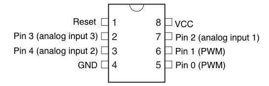
Pin 1-3 of the chip will not be connected.

Pin 4 of the chip will be the ground, It will be connected to the ground from the power source, led, buzzer and ultrasonic sensor.

Pin 5 of the chip will be connected to the Anode of the Led. The Cathode of the Led will be connected to the anode of the buzzer. The cathode of the buzzer will be connected to the ground. This way, the buzzer will buzz when the Led turns on.

Pin 6 of the chip will be connected to the UltraSonic Sensor (Sensor Pin).

Pin 7 of the chip will not be connected.

Pin 8 of the chip will be the Vcc or where the Vcc from your Type B USB Port will be going to. A switch should be placed between this pin and the Vcc from the USB Port.

Step 2)

Break at the necassary places to avoid the circuit from crossing each other. Mine consists of 7 break point.

After all connections is done, you should have  something like this. Note, this is my layout, yours may be different. As long as the components are connected according to the steps above, it should be working fine.


Step 3)
Install your arduino as ISP . Refer to my previous post. The AtTiny can now be programmed with the shield and Arduino. Copy the code below to your Arduino IDE and upload to your AtTiny. Proper steps for downloading to the AtTiny can be found in my previous post.

                                                     Copy code from below this line onwards:
const int pingPin = 1;

void setup() {
  pinMode(0, OUTPUT);            //Led
}

void loop()
{
  long duration, inches, cm;

  pinMode(pingPin, OUTPUT);
  digitalWrite(pingPin, LOW);        
  delayMicroseconds(2);
  digitalWrite(pingPin, HIGH);
  delayMicroseconds(5);
  digitalWrite(pingPin, LOW);

  pinMode(pingPin, INPUT);
  duration = pulseIn(pingPin, HIGH);

  // convert the time into a distance
  inches = microsecondsToInches(duration);
  cm = microsecondsToCentimeters(duration);
 
  delay(5);
 
  if(cm<50 && cm>20)
  {
  digitalWrite(0, HIGH);   // turn the LED on (HIGH is the voltage level)
  delay(200);              // wait for a second
  digitalWrite(0, LOW);    // turn the LED off by making the voltage LOW
  delay(200);              // wait for a second
 
  }
 
  else if(cm<20)
  {
  digitalWrite(0, HIGH);   // turn the LED on (HIGH is the voltage level)
  delay(80);              // wait for a second
  digitalWrite(0, LOW);    // turn the LED off by making the voltage LOW
  delay(80);              // wait for a second
 
  }

}

long microsecondsToInches(long microseconds)
{
  return microseconds / 74 / 2;
}

long microsecondsToCentimeters(long microseconds)
{
  return microseconds / 29 / 2;
}
                                                             Copy code till above this line

Upload the code to your AtTiny 85.

Step 4)
   Your board shall now work as follows: I've not connected the buzzer in the video.


Step 5)
As mine is an incoming people sensor. I'm placing it near my room door.


This is the final outcome. My very own alarm that alerts me when someone is approaching or entering the room.


Hope you'll give this project a try. Cheers!

Wednesday, December 17, 2014

In this post I'll be showing you how to use your AtTiny Shield with an Arduino Uno. Its really not that hard.

Things required:
1) AtTiny Shield (Refer to my previous post on how to create this)
2) Arduino Uno
3) Arduino IDE Environment
4) USB Cable

Step 1
   Connect the Arduino Uno to your computer and ensure that the board is set as Arduino Uno.


Step 2
   Click on Files followed by examples followed by ArduinoISP.


Step 3
   Click on upload. (Note: At this point there should be nothing connected to your Arduino other than the USB Cable.)


Step 4
   Once the upload is complete, remove USB from Computer. Mount the AtTiny Shield on the Arduino Uno. Do not forget to mount your AtTiny chip on the shield. I've forgotten to mount it in the picture below. Reconnect the USB to your computer.


Step 5
   Click on Tools>Board and click on the appropriate AtTiny that you are using. For my case, It would be AtTiny 85.


Step 6
   Click on tools>Programmer followed by Arduino as ISP.


Step 7
   You may now upload your AtTiny code. However, do take note. Upon uploading, the following error will occur:

avrdude: please define PAGEL and BS2 signals in the configuration file for part ATtiny85

Do not be panic. It is safe to ignore this error. Your AtTiny is now ready for use. Cheers!
In one of my previous post, I shared how to create an AtTiny Shield. You might be wondering how do you prepare the Arduino IDE so that it is usable with the Shield. I''m going to cover that in this post. It can be quite complicated. I've included screenshot for better understanding.

Things required:
1) Arduino IDE Environment
2) attiny-master.zip

Step 1
   Click on the "attiny-master.zip" link above and download it. Save it to somewhere where it is easy to find. We're going to need it later.

Step 2
   Start your Arduino IDE Environment and click on File followed by Preferences.


Step 3
   Open that exact same directory of your "Sketchbook Location" on your computer file explorer. Create a new folder and name it "hardware". (Note: You don't have to create a new folder if a folder named hardware has already existed)


Step 4
   Extract the content of the zip file (attiny-master.zip) into the hardware folder. Note: A folder named "attiny" and NOT "attiny-master" should be in the hardware folder. You should have a directory of something like this:


Step 5
   Close any Arduino IDE Software if you have it running. Restart the Arduino IDE. Click on Tools followed by Board. You should have the all the AtTiny option there.


Basically, that's about  it. Your Arduino Software is now ready to program AtTiny chips.

Sunday, November 9, 2014

Hi!

Its been a long time since I last posted in this Blog. In this post, I'll be sharing with you a simple code for arduino uno that you can play around with. This codes are used with the Leds. Basically, a few modifications have been done from the built-in blink code. The setup of my Leds are as follow.
The Green, Yellow, Red and Red Leds have been wired to Arduino pin 4,3,2 and 1 respectively. The negative side of the Leds are common ground to Arduino Ground Pin.


With the usage of simple "for"" loop function, it is possible to make each of the led blink multiple times individually. For example, with this code: 

Beginning of code: Copy from below onwards.

int count;

// the setup function runs once when you press reset or power the board
void setup() {
  // initialize digital pin 4,1,2,3 as an output.
  pinMode(4, OUTPUT);
  pinMode(1, OUTPUT);
  pinMode(2, OUTPUT);
  pinMode(3, OUTPUT);
}

// the loop function runs over and over again forever
void loop() {
    for(count=0;count<3;count++)
    {
    digitalWrite(1, HIGH);   // turn the extreme right (first) led on
    delay(250);              
    digitalWrite(1, LOW);    // turn the LED off by making the voltage LOW
    delay(250);              
    };
    
    for(count=0;count<10;count++)
    {
    digitalWrite(2, HIGH);   // turn the second LED on (HIGH is the voltage level)
    delay(50);              
    digitalWrite(2, LOW);    // turn the LED off by making the voltage LOW
    delay(50);      
    }      
    
    for(count=0;count<5;count++)
    {
    digitalWrite(3, HIGH);   // turn the third LED on (HIGH is the voltage level)
    delay(100);              
    digitalWrite(3, LOW);    // turn the LED off by making the voltage LOW
    delay(100);      
    }

  digitalWrite(4, HIGH);   // turn the final LED on (HIGH is the voltage level)
  delay(100);              
  digitalWrite(4, LOW);    // turn the LED off by making the voltage LOW
  delay(100);      
}

End of code:Copy till above this line.

You can make the Leds blink as such (starts at 00;02) :


By comparing between the Leds, you can easily tell that the number of blinks, duration of each blink and the speed of each blink is different.

Another example of code will be this:
                                              Beginning of code: Copy from below onwards.
int count;

void setup(){
  pinMode(1,OUTPUT);
  pinMode(2,OUTPUT);
  pinMode(3,OUTPUT);
  pinMode(4,OUTPUT);
  }
  
 void loop(){
    digitalWrite(1,HIGH);     //Test start
    digitalWrite(2,HIGH);
    digitalWrite(3,HIGH);
    digitalWrite(4,HIGH);
    delay(1000);
    digitalWrite(1,LOW);
    digitalWrite(2,LOW);
    digitalWrite(3,LOW);
    digitalWrite(4,LOW);      //Test end
    
    for(count=0;count<3;count++)
    {
    digitalWrite(1,HIGH);     //Sweep left start
    delay(50);
    digitalWrite(1,LOW);
    digitalWrite(2,HIGH);
    delay(50);
    digitalWrite(2,LOW);
    digitalWrite(3,HIGH);
    delay(50);
    digitalWrite(3,LOW);
    digitalWrite(4,HIGH);
    delay(50);
    digitalWrite(4,LOW);      //sweep left end
    
    digitalWrite(4,HIGH);     //Sweep right start
    delay(50);
    digitalWrite(4,LOW);
    digitalWrite(3,HIGH);
    delay(50);
    digitalWrite(3,LOW);
    digitalWrite(2,HIGH);
    delay(50);
    digitalWrite(2,LOW);
    digitalWrite(1,HIGH);
    delay(50);
    digitalWrite(1,LOW);      //sweep left end
    }
    
    for(count=0;count<20;count++)
    {
    digitalWrite(1,HIGH);     //Blink
    digitalWrite(2,HIGH);
    digitalWrite(3,HIGH);
    digitalWrite(4,HIGH);
    delay(20);
    digitalWrite(1,LOW);
    digitalWrite(2,LOW);
    digitalWrite(3,LOW);
    digitalWrite(4,LOW);      //Blink
    delay(20);
    }
    
    
    for(count=0;count<5;count++)
    {
    digitalWrite(1,HIGH);    //both end start
    digitalWrite(4,HIGH);
    delay(250);
    }
    digitalWrite(1,LOW);
    digitalWrite(4,LOW);     //both end end

    for(count=0;count<5;count++)
    {
    digitalWrite(2,HIGH);    //center on start
    digitalWrite(3,HIGH);
    delay(250);
    }
    digitalWrite(2,LOW);
    digitalWrite(3,LOW);     //center on end
    
    for(count=0;count<5;count++)
    {
    digitalWrite(2,HIGH);    //center blink start
    digitalWrite(3,HIGH);
    delay(100);
    digitalWrite(2,LOW);
    digitalWrite(3,LOW);
    delay(100);              //center blink end
    }
    delay(1000);                                                                                  
      
    digitalWrite(4,HIGH);    //move right start
    delay(500);
    digitalWrite(4,LOW);
    digitalWrite(3,HIGH);
    delay(500);
    digitalWrite(3,LOW);    
    digitalWrite(2,HIGH);    //move right end
    digitalWrite(1,HIGH);    //opponent on
    delay(250);
    
    digitalWrite(1,HIGH);    //opponent alive
    
    for(count=0;count<5;count++)
    {
    digitalWrite(2,HIGH);    //attacker dying start
    delay(100);
    digitalWrite(2,LOW);     //attacker dying end
    delay(100);
    }    
    digitalWrite(2,LOW);
    
    digitalWrite(1,HIGH);    //move left start
    delay(500);
    digitalWrite(1,LOW);
    digitalWrite(2,HIGH);
    delay(500);
    digitalWrite(2,LOW);    
    digitalWrite(3,HIGH);    //move left end

    digitalWrite(4,HIGH);    //opponent on
    delay(250);
    
    for(count=0;count<5;count++)
    {
    digitalWrite(3,HIGH);
    delay(100);
    digitalWrite(3,LOW);
    delay(100);  
    }
    
    digitalWrite(4,HIGH);    //opponent survive
    delay(250);
    digitalWrite(4,LOW);
    digitalWrite(3,HIGH);
    delay(250);
    digitalWrite(3,LOW);
    digitalWrite(2,HIGH);
    delay(250);
    
    for(count=0;count<10;count++)
    {
    digitalWrite(2,HIGH);
    delay(100);
    digitalWrite(2,LOW);
    delay(100);
    }
    
    for(count=0;count<10;count++)
    {
    digitalWrite(2,HIGH);
    digitalWrite(1,HIGH);
    digitalWrite(3,HIGH);
    delay(100);
    digitalWrite(2,LOW);
    digitalWrite(1,LOW);
    digitalWrite(3,LOW);
    delay(100);
    }
    
     for(count=0;count<10;count++)
    {
    digitalWrite(2,HIGH);
    digitalWrite(4,HIGH);
    digitalWrite(1,HIGH);
    digitalWrite(3,HIGH);
    delay(100);
    digitalWrite(2,LOW);
    digitalWrite(1,LOW);
    digitalWrite(3,LOW);
    digitalWrite(4,LOW);
    delay(100);
    }
    
    delay(1000);
  }
    End of code:Copy till above this line.

With the code above, you can make the Leds blink as such (starts at 00;14) : 


That is all for now. Enjoy changing the delay and pattern of the Leds. Cheers!

Thursday, April 24, 2014

Hi. In this post, I'll be sharing on how to make your very own headphones that will follow the highest sound according to the music thats being played. This is rather an easy and straight forward project. Probably a rating of  3 out of 10 in difficulty level. Suitable for music lover (like me). Lets get started.

Components required:
1) Small Strip Board
2) 3.5mm Standard audio jack (Male)
3) Wires for Audio input
4) Wires for connecting the LED Strip to the stripboard
5) LED strip
6) 1 TIP 41 Transistor
7) Headphones (Obviously)
8) 3.5mm audio splitter
9) 9 Volt battery along with its connector
10) Probably some tapes

Tools required:
1) Soldering Tool
2) Soldering stand
3) Soldering wire
4) Wire stripper

Alright. Here are the steps.

Step 1)  Take the 3.5mm male audio jack and twist it open. Once its opened, you should see this:


Using one wire, connect it to the longest metal and solder it to secure the connection. Take another wire and connect to either one of the remaining metal joint. Here's how it should look like:


Step 2) Take the transistor and mount it on the small strip board. Connect the wiring as follow. Ignore the individual LED. Just replace it with the LED Strip. Ignore the 12 Volt too. I'm using a 9 Volt battery.


If you've wired it all up. It should look like this:


The yellow and green are from the audio jack. The black and red wire at the extreme right links to the battery. I have two wires at the center pin because I'm lighting up both red and blue to create a purple light colour effect. One of the wires connected to the positive of the battery goes to the LED Strip.

Step 3) Just solder everything and your circuit is ready. Just have to do some final touches. I'm using a double sided tape to secure all the circuitry as well as the battery to the left side of the headphones. Image as follows:


Step 4) Connect both the headphone and the audio jack that links to your circuitry to the audio splitter and plug it to any device and watch the light dance. Totally no software or programming involved. :)

A picture of an audio splitter.


Saturday, April 12, 2014


In this post, I'll be sharing how to to make a 4 X 4 X 4 LED cube. It may look complicated, but trust me. Take one step at a time and your cube will be ready in no time.

Components required:
1) 70 LED cube (6 spares in case there is some faulty ones)
2) 4 100 Ohm resistor
3) 1 Perf Board (The ones where all the holes are individually coppered. No linkages between 2 holes)
  *I'm using a stripboard to reduce the usage of wires. This is more challenging as you have to create a path for all 16 base legs without short-circuiting each other.
4) Lots and lots of wires. approximately 1 metre.
5) 1 Arduino Uno (along with its cable)
6) A piece of wood for the jig/template.
  *In here I'll be using a styrofoam box used in the packaging of items. I'll also be using a pen to make the holes. Cheap, fast and neat.

Tools required:
1) Breadboard
2) Wire Stripper
3) Wire Cutter
4) Drill according to the size of your LED.
5) Solder wire
6) Solder tool
7) Solder pump (if necessary)

Alright. Let the fun begin!

Step 1) Take the piece of wood and draw out the square. Making sure the length are all the same and the distance between 2 junctions is constant throughout. (I'm using styrofoam)


Step 2) Take the drill and makes holes at all the junctions. Including the 't','T' & 'L' junctions. You should have about 16 holes by now. (Mine was poked with a pen)


Step 3) Stick LED into each of the holes.


Step 4) Bend all the cathode legs down such that you have a square at the side. Bend the cathode legs of the 4 centre LED such that they all point to a different direction.


Step 5) Solder all the cathode legs together. Careful not to hit any of the anode legs. Carefully remove the completed layer from the jig/template.


Step 6) Repeat step 3 to step 5 for the other 3 layers. However, do take note that 2 of the layers should have a different centre structure. Instead of following the first and second layer, the 4 centre LED on the 3rd and 4th layer should have its cathode legs bent to the adjacent side of the square. (Forgive one of my layers. Removed 2 of the leds after burning it during soldering.) This alternating pattern is important as they will be built up with the alternating patterns.


Step 7) Bend all the anode legs at the side outwards and the 4 centre LED anode legs in the anti-clockwise direction. Pick one layer and place it back in the jig so it wont move around. Take another layer with different structure and stack it on top of the first layer. Solder the 4 anode legs at the corners followed by all the ones in between.


Step 8) Take another different structure from the second layer and repeat the soldering for the third and final layer. By now, you should have this...


Step 9) Take the Perf Board and mount the cube on it. Solder the protruding legs at the bottom of the Perf board. (I'm using a Strip Board)


Bottom view


Step 10) Connect a wire to the holes beside each of the legs. Bring each of the other end of the wire to the end of the board. Leaving just one row at the end for the connectors. Solder the connectors.


 Note: If you are using Perf board, there should be about 16 wires. Mine have little because I'm using the copper strip below. If you are using stripbooard like mine, here's a photo of mine. You have to do a lot of breakings and might need to short-circuit the row beside to create a path as seen in mine. Complicated but thats the fun part right? Hehe.


Step 11) Place the 4 resistors at the corner and bring a wire up to each layer from each resistor. The other end of the resistor have to be wired to the end of the corner board too. By now, you should have 20 connectors connected. 16 to the anodes and 4 to the resistors.


Step 12) Now you're ready to wire up your connector to the wires.


Step 13) Starting from the extreme left. Wire it to the arduino from digital pin 13 to 0. Continuing the flow to Analog input A5 to A0.


Your 4 X 4 X 4 LED cube is now ready. Enjoy!

Sunday, February 2, 2014

In this post, I'll be sharing with you on how to do your own AtTiny 45/85 ISP shield. Its very easy and cheap. Alright, let's begin.

Components required:
1) 1 8 pin IC Socket
2) 1 10 micro-farad capacitor
3) Some wires
4) Single Row Straight Header (About 14 pins is enough) ( 1 at 6 pins and the other at 8 pins)
5) Strip board (13 by 20 holes) ( The side with 20 holes running parallel to the copper strip)


Tools required:
1) Solder Tool
2) Solder Wire
3) Solder pump (if necessary)
4) Wire cutter

Step 1) Take the single row straight header.


Just knock the short side inwards so that the bottom pin will be extra long.


Step 2) Place the component as follows:
From the top view of the stripboard:
2.1) Place the 6 pin header 1 hole away from the bottom left edge.
2.2) Place the 8 pin header 2 hole away from the top right edge.
2.3) Place the capacitor legs into the first and fifth leg of the 6 pin header with the negative side on the fifth leg column.
2.4) Place the IC Socket 4 holes below the 8 pin header with Pin 1 and 8 aligned to the 8 pin header's second pin from the left.
2.5) Place a wire connecting the extreme left of the 6 pin header to the extreme right of the 8 pin header.
2.6) Place a wire connecting the 3rd pin of the 6 pin header (from the left) to the IC Socket's pin 8.
2.7) Place a wire connecting the 3rd pin from the right of the 8 pin header to the IC Socket's pin 1.

 By now. This is what you should be having...


If it is similar to the one in the picture, you can begin soldering the components.

Step 3) Turn the board upside down and break the circuit as follows:

3.1) Begin breaking from pin 1 of the ic socket all the way for 9 consecutive holes heading towards the IC's pin 4 direction. (Refer to diagram)

 3.2) Break above the capacitors leg at pin 1 from the extreme left of the 6 header pin.


3.3) Break just below the second pin from the left of the 8 pin header.


3.4) Your breakage point should be as follow:


Step 4) Your AtTiny 45/85 ISP Shield is ready. You can now begin programming your AtTinys.